Ring cores
Ring cores are frequently used for inductors with a defined L value, predetermined frequency stability and thermal and temporal constancy. Medium and high perm manganese-zinc ferrites and medium to low perm nickel-zinc ferrites are the materials used for ring cores.
The recommended materials are:
| Frequency range | Material |
|---|---|
| 10kHz – 1MHz | K2005, K4000, K5500, K6000,K7000, K10000 |
| 1MHz – 200MHz | K14, K40, K250, K800 |
Ferrite ring cores are used for highly symmetrical transformers, for impulse and wideband transformers, for common-mode chokes for damping of radio interference and now increasingly also for the development of power transformers.
The following favourable frequency ranges are predetermined for materials K2001, K2004, K2006 and K2008:
| Frequency range | Material |
|---|---|
| 20 – 100 kHz | K2004 |
| 50 – 200 kHz | K2006 |
| 50 – 300 kHz | K2008 |
| 300 – 1000 kHz | K2001 |
In order to prevent short-circuits when winding and to increase the insulation strength, ring cores can also be supplied with parylene or lacquer coating. Dimensions and insulation of ferrite ring cores are in compliance with IEC 61604.
If not otherwise agreed upon, the following electrical insulation strenght apply to coated toroids:
| outer diameter ≤ 10 mm: | ≥ 1,0 kV |
| outer diameter ≤ 20 mm: | ≥ 1,5 kV |
| outer diameter > 20 mm: | ≥ 2,0 kV |
In the case of AC tests, the insulation strengths apply to the effective value. It complies with IEC 61604.
Nickel-zinc ferrites are supplied without coating due to their high electrical resistance. In contrast, manganese-zinc ferrites can be supplied with parylene or lacquer coating. The layer thickness leads to an enlargement of the outer diameter and the height and to a decrease of the inner diameter and amounts to with parylene approx. 30 – 40 µm as well as with the lacquer approx. 0.3 – 0.6 mm. The applied lacquer usually leads to a loss of permeability, which makes it necessary to expand the AL tolerance values in relation to uncoated cores.
The stated core heights are for orientation and can be changed on request. The guaranteed parameters for power applications apply to the winding data stated by the manufacturer, the predetermined testing frequency, excitation and temperature.
| Type | Drw. no. | nominal AL values / nH | datasheet | ||||||
|---|---|---|---|---|---|---|---|---|---|
| K2006 | K2008 | K4000 | K5500 | K6000 | K7000 | K10000 | |||
| R 2.5/1.5/1 | 1 | 410 | 610 | 1020 | |||||
| R 3.5/1.8/2,4 | 1 | 530 | 800 | 1300 | |||||
| R 4.1/2.2/1.6 | 1 | 780 | 1150 | 1950 | |||||
| R 5,8/3/1.5 | 1 | 790 | 1150 | 1950 | |||||
| R 6.3/3.8/2.5 | 1 | 1000 | 1500 | 2500 | |||||
| R 8/4/3 | 1 | 1650 | 2450 | 4150 | |||||
| R 10/6/4 | 1 | 850 | 900 | 1600 | 2200 | 2450 | 2700 | 4050 | |
| R 12.5/7.5/5 | 1 | 1050 | 1150 | 2000 | 2800 | 3050 | 3300 | 5100 | |
| R 14/9/5 | 1 | 900 | 1000 | 1750 | 2400 | 2650 | 2850 | 4400 | |
| R 16/9.6/6.3 | 1 | 1350 | 1450 | 2550 | 3500 | 3850 | 4150 | 6400 | |
| R 19/11/8 | 1 | 1800 | 2000 | 3450 | 4800 | 5250 | 5650 | 8700 | |
| R 20/10/7.4 | 1 | 2150 | 2350 | 4100 | 5600 | 6150 | 6650 | 10250 | |
| R 21.5/10.3/7.5 | 1 | 2200 | 2400 | 4150 | 5750 | 6250 | 6850 | ||
| R 22/10/6 | 1 | 1800 | 2000 | 3400 | 4700 | 5150 | 5550 | ||
| R 23/14/7 | 1 | 1450 | 1600 | 2750 | 3800 | 4150 | 4500 | ||
| R 25/15/10 | 1 | 2100 | 2350 | 4050 | 5600 | 6100 | 6600 | ||
| R 26/14,5/10 | 1 | 2450 | 2650 | 4650 | 6400 | 7000 | 7600 | ||
| R 27/14.5/8.5 | 1 | 2050 | 2300 | 3950 | 5450 | 5950 | 6850 | ||
| R 28/18/19 | 1 | 3500 | 6700 | 9200 | 10050 | 10900 | |||
| R 29/19/7.5 | 1 | 1300 | 2500 | 3450 | 3800 | 4100 | |||
| R 30/11.5/5.3 | 1 | 2000 | 3850 | 4800 | 5750 | 6250 | |||
| R 31.5/19/12.5 | 1 | 2650 | 5050 | 6300 | 7550 | 8200 | |||
| R32.5/13/7 | 1 | 2550 | 4850 | 6050 | 7250 | 7850 | |||
| R 34/20.5/12.5 | 1 | 2650 | 5050 | 6050 | 7550 | 8200 | |||
| R 36/23/15 | 1 | 2800 | 5350 | 6700 | 8050 | 8700 | |||
| R 40/24/16 | 1 | 3400 | 6500 | 7850 | 9800 | 10600 | |||
| R 42/26/12.5 | 1 | 2450 | 4650 | 5850 | 7000 | 7600 | |||
| R 50/30/20 | 1 | 4250 | 8150 | 9800 | 12250 | 13250 | |||
| R 56/32/18 | 1 | 4050 | 7700 | 9650 | 11550 | 12550 | |||
| R 58.3/40.8/17.6 | 1 | 2600 | 5000 | 6250 | 8150 | ||||
| R 63/38/12,5 | 1 | 2650 | 5050 | 6050 | 8200 | ||||
| R 80/40/15 | 1 | 4350 | 8300 | 10500 | |||||
| R 102/65,8/15 | 1 | 2750 | 5250 | 6300 | |||||
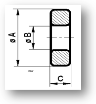
| Drawing 1 |


Kaschke Components GmbH • Kaschke Components GmbH • Rudolf-Winkel-Str. 6 • 37079 Göttingen • Telefon +49 551 5058 6 • Telefax +49 551 65756