Planar components for SMPS
In the design of a low profile SMPS transformers or storage choke, we highly recommend the use of our ferrite planar cores. The use of this core shape allows you a high power and current density, combined with a substantially reduced overall height.
The improved surface to volume ratio provides outstanding electric performance. In addition, it increases uniformity of electrical parameters and as well the reliability and lifetime of the components.
These characteristics allow a very flexible and versatile use of the range of Kaschke Planar Cores when constructing high power inductive components. By choosing the low loss high frequency ferrite material you will achieve the optimal solution in the frequency range of 100-1000 kHz.
Advantages of the planar cores
- Reduced height
- High power density
- Reduced power losses up to high operating frequencies
- Outstanding thermal properties due to extended surfaces
- Reduced leakage flux
- High yield and stability of electrical parameters
- High reliability
Application note
Planar Core Series: The most favoured products are types PE/PI 18, 22, 32, 38, 43 and 64 available as E- or I-Core. Other types of the Planar Core Family, all standardized according to IEC 61860, are available on request. Air gap: On request,all PE-Cores can be supplied with an airgap.
Material Specificaton
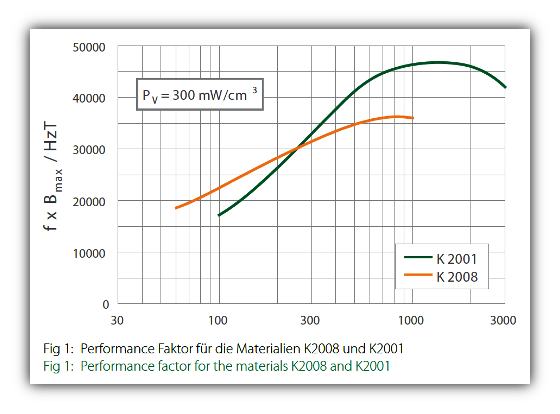
Our range of Planar Cores were designed using the Kaschke low loss power ferrite materials K2008 and K 2001. The material K 2008 is suitable for a application frequency up to 500 kHz, while K2001 designed for the use up to 1 MHz.
Fig. 1 Shows the performance factor of both.
To calculate the Performance factor, firstly measure for each frequency the inducation B300, which is defined as the induction level core losses of 300mW/cm3. The performance factor is calculated by multiplying B300 with the frequency. The performance factor vs. frequency plot enables a comparison of power materials and the choice of the optimal frequency for your application.
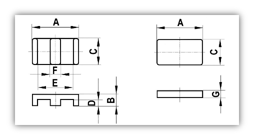
| Dimension[mm] | PE / PI 18 | PE / PI 22 | PE / PI 32 | PE / PI 38 | PE / PI 43 | PE / PI 64 |
|---|---|---|---|---|---|---|
| A | 17.65 – 18.35 | 21.40 – 22.20 | 31.10 – 32.40 | 37.30 – 38.90 | 42.90 – 44.10 | 64.0 ± 1.3 / 63.8 ± 1.3 |
| B | 3.90 – 4.10 | 5.60 – 5.80 | 8.10 – 8.40 | 8.10 – 8.40 | 9.35 – 9.65 | 10.2 ± 0.13 |
| C | 9.80 – 10.20 | 15.50 – 16.10 | 24.85 -25.95 | 24.85 – 25.95 | 27.30 – 28.50 | 50.8 ± 1 / 50.3 ± 1 |
| D | 1.90 – 2.10 | 3.10 – 3.30 | 4.30 – 4.60 | 4.30 – 4.60 | 5.25 – 5.55 | 5.1 ± 0.13 |
| E | 13.70 – 14.30 | 16.40 – 7.20 | 30.20 – 31.40 | 30.20 – 31.40 | 34.70 – 36.30 | 53.8 ± 1.1 |
| F | 3.90 – 4.10 | 4.90 – 5.10 | 7.40 – 7.80 | 7.40 – 7.80 | 7.90 – 8.30 | 10.2 ± 0.2 |
| G | 1.90 – 2.10 | 2.40 – 2.60 | 3.65 – 3.95 | 3.65 – 3.95 | 3.95 – 4.25 | 5.08 ± 0.13 |
| Core parameter | PEE18 | PEI18 | PEE22 | PEI22 | PEE32 | PEI32 | |
|---|---|---|---|---|---|---|---|
| Core facotr | C1 =Σ l/A[mm-1] | 0.618 | 0.513 | 0.414 | 0.332 | 0.318 | 0.136 |
| Eff. path length | Ie [mm] | 24.3 | 20.3 | 32.5 | 26.1 | 41.4 | 69.6 |
| Eff. cross section | Ae [mm2] | 39.3 | 39.5 | 78.3 | 78.9 | 130 | 511 |
| Min. cross section | Amin [mm2] | 38.9 | 38.9 | 77.9 | 77.9 | 128 | 511 |
| Eff. magn. Volume | Ve [mm3] | 955 | 802 | 2540 | 2050 | 5390 | 35500 |
| K 2008 | |||||||
| AL-Value | ± 25% [nH] | 3500 | 3800 | 5500 | 6350 | 7150 | 16950 |
| losses PCORE [W] | bei f=100kHz, B=200mT, T=100°C | ≤ 0.48 | ≤ 0.40 | ≤ 1.3 | ≤ 1.0 | ≤ 2.7 | ≤ 17.8 |
| losses PCORE [W] | bei f=500kHz, B=50mT, T=100°C | ≤ 0.19 | ≤ 0.16 | ≤ 0.51 | ≤ 0.41 | ≤ 1.1 | |
| K 2001 | |||||||
| AL-Value | ± 25% [nH] | 2500 | 2750 | 3850 | 4550 | 5000 | |
| losses PCORE [W] | bei f=500kHz, B=50mT, T=100°C | ≤ 0.14 | ≤ 0.12 | ≤ 0.38 | ≤ 0.31 | ≤ 0.81 | |
| losses PCORE [W] | bei f=1MHz, B=25mT, T=100°C | ≤ 0.15 | ≤ 0.13 | ≤ 0.41 | ≤ 0.33 | ≤ 0.86 | |
| Core parameter | PEE38 | PEI38 | PEE43 | PEI43 | PEE64 | PEI64 | |
|---|---|---|---|---|---|---|---|
| Core factor | C1 =Σ l/A [mm-1] | 0.270 | 0.225 | 0.267 | 0.220 | 0.156 | 0.136 |
| Eff. path length | Ie [mm] | 52.4 | 43.6 | 61.1 | 50.4 | 79.7 | 69.6 |
| Eff. cross section | Ae [mm2] | 194 | 194 | 229 | 229 | 511 | 511 |
| Min. cross section | Amin [mm2] | 192 | 192 | 225 | 225 | 511 | 511 |
| Eff. magn. Volume | Ve [mm3] | 10200 | 8440 | 14000 | 11500 | 40700 | 35500 |
| K 2008 | |||||||
| AL-Value | ± 25% [nH] | 8450 | 11000 | 8550 | 10300 | 16100 | 16950 |
| losses PCORE [W] | bei f=100kHz, B=200mT, T=100°C | ≤ 5.1 | ≤ 4.2 | ≤ 7.0 | ≤ 5.8 | ≤ 20.4 | ≤ 17.8 |
| losses PCORE [W] | bei f=500kHz, B=50mT, T=100°C | ≤ 2.1 | ≤ 1.7 | ≤ 2.8 | ≤ 2.3 | ||
| K 2001 | |||||||
| AL-Value | ± 25% [nH] | 5950 | 7050 | 6000 | 7250 | ||
| losses PCORE [W] | bei f=500kHz, B=50mT, T=100°C | ≤ 1.5 | ≤ 1.3 | ≤ 2.1 | ≤ 1.7 | ||
| losses PCORE [W] | bei f=1MHz, B=25mT, T=100°C | ≤ 1.6 | ≤ 1.4 | ≤ 2.3 | ≤ 1.9 | ||
| Material | Ordering Code | ||||||
|---|---|---|---|---|---|---|---|
| PE / PI 18 | PE / PI 22 | PE / PI 32 | PE / PI 38 | PE / PI 43 | PE / PI 64 | ||
| K2008 | PE-Core | 382184 001028 | 382226 001028 | 382326 501028 | 382388 001028 | 382439 501028 | 382641 001028 |
| PI-Core | 382182 090028 | 382222 590028 | 382323 290028 | 382383 890028 | 382434 190028 | 382645 190028 | |
| K2001 | PE-Core | 382184 001021 | 382226 001021 | 382326 501021 | 382388 001021 | 382439 501021 | 382641 001021 |
| PI-Core | 382182 090021 | 382222 590021 | 382323 290021 | 382383 890021 | 382434 190021 | 382645 190021 | |
Inductive components
We can highly recommend the design of inductive components based upon our planar core series. Typical components are storage chokes and transformers. Windings can be constructed by using multilayer PCBs, Disc-winding or preproduced stamped copper plates, or a mixture of both.
The range of planar cores we offer generate a lot options for the design of planar magnetics. Our transformers can also be designed to comply with EN 60950 safety standards.